Schematics, BOM and code on GitHub
Building guide
For programming: connect the USB cable from your computer to Nano or NodeMCU and pull out the MCU_VIN jumper when you upload the sketch to Nano or NodeMCU, otherwise you might experience errors. Put the jumper back when the upload is done.
Building on breadboard or perf board:
1) Download schematics and BOM from GitHub. Get familiar with the schematics and make sure you understand where each wire goes.
2) Build I2C bus (3V3 power, ground, SCL, SDA) that is used by devices connected to Nano.
3) Connect I2C devices (temp&humidity sensor, light sensor, OLED screen and RTC module) to Nano.
4) Test device operation with "testSensors_Nano" sketch. If you run into trouble, you can use "I2C_list_devices" sketch to debug the issue.
5) Connect buttons and buzzer.
6) Test buttons and buzzer operation with "testButtons_Nano" sketch.
7) Connect Nano and NodeMCU using voltage converter.
8) Test connection between Nano and NodeMCU using "testSerialSend_Nano" sketch on Nano and "testSerialReceive_NodeMCU" on NodeMCU.
9) Create ThingSpeak account and run test program "testThingSpeak_NodeMCU".
10) If you are using Sonoff, set your Sonoff switch and check it is working (steps 1-3 in this instructable: www.instructables.com/id/Control-Sonoff-From-Raspberry-Pi/ ). Use the very same rules as the ones in the instructable when you set up your Sonoff.
11) Test Sonoff control using sketch "testSonoff_NodeMCU".
12) Upload "livduino_Nano" and "livduinoNode_MCU" sketches on Nano and NodeMCU respectively.
|
Building on LiVduino PCB:
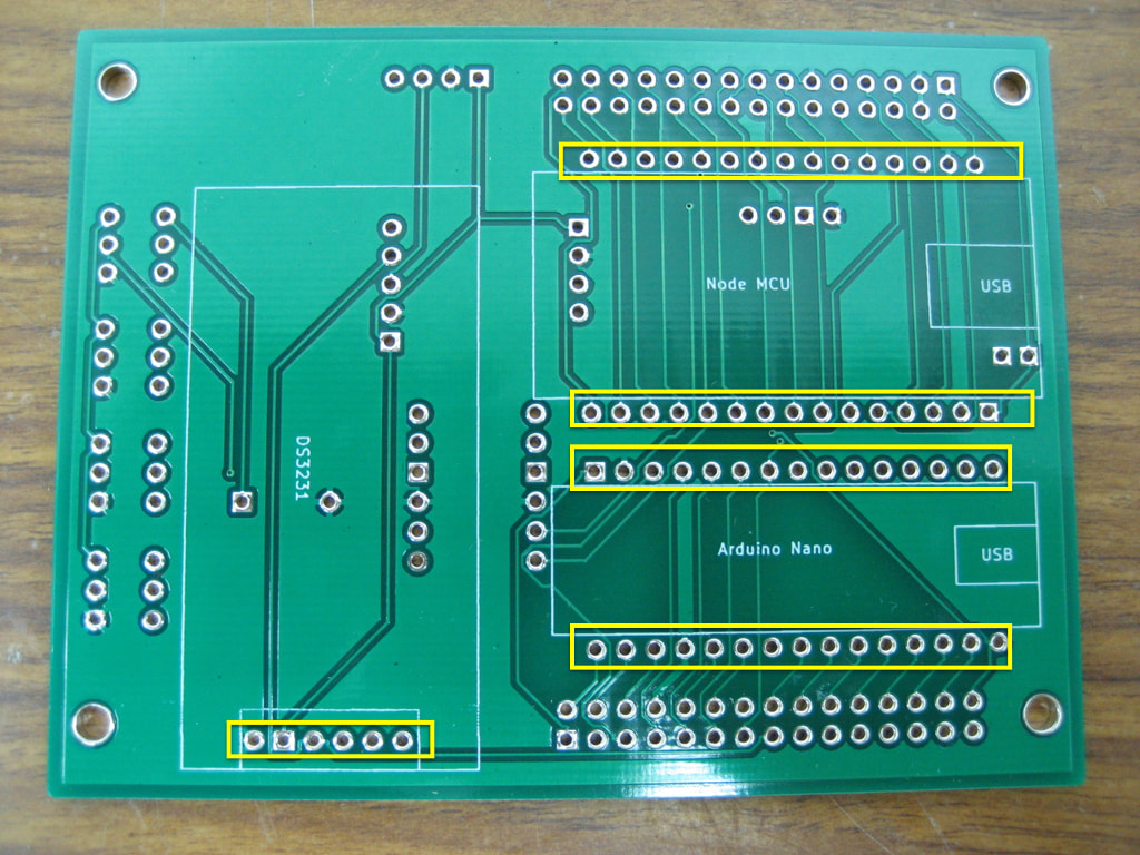
Make sure you identify the place for every component before you start soldering. There are parts on both sides of PCB, so if you are not following the suggested soldering order, make sure that the parts you are soldering will not cover soldering points for parts on the other side. Footprint for parts are indicated in white. The rectangular soldering points are VCC points (5V or 3V3).
We suggest the following order of soldering: Back
1) All parts on back use connectors. Solder 15 pin connectors for Nano and NodeMCU on the back first. Insert Nano and NodeMCU into the connectors, this will make your task easier. 2) Solder 6 pin right angle connector for DS3231. |
|
|
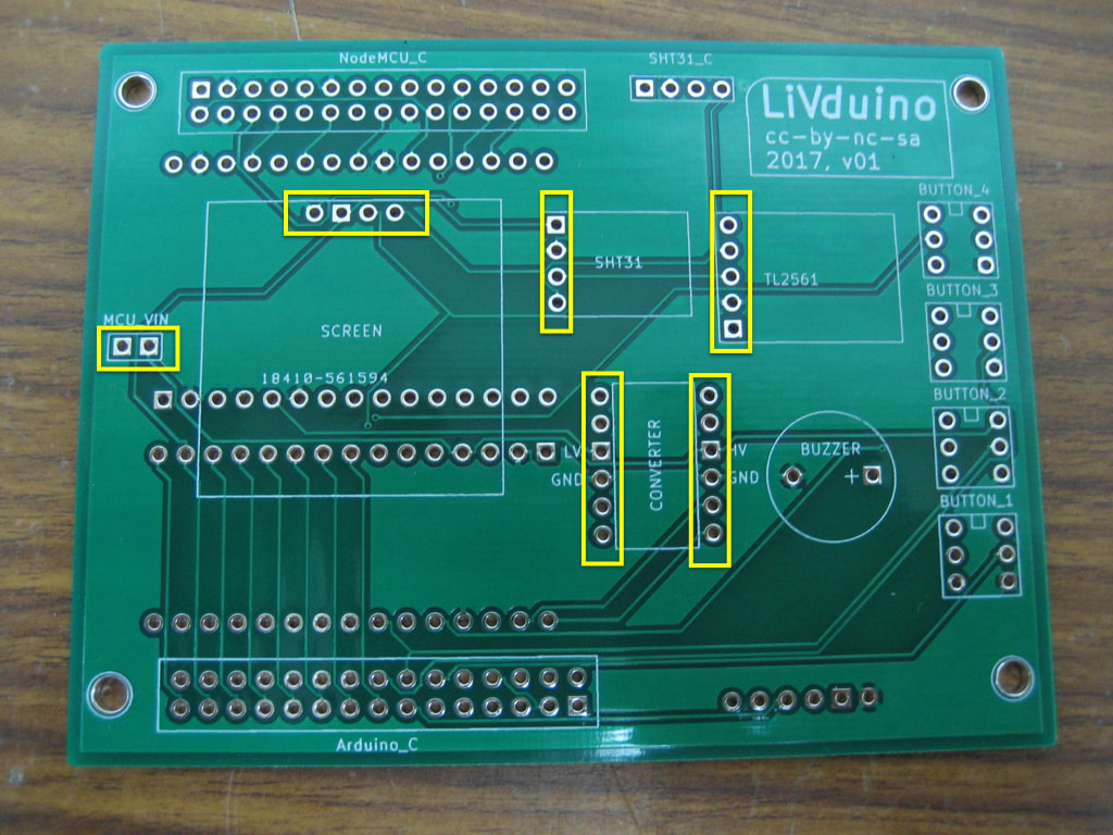
Front
Parts can be soldered directly on the front of PCB or you can use header connectors for them. 3) Solder OLED screen, SHT31 and TLS2561 sensors. 4) Solder voltage converter. Pay attention so that LV and HV pins on the converter match the markings on PCB. 5) Solder buzzer. Make sure that the + pin of the buzzer matches the markings on PCB. 6) Solder 2 pin connector for MCU VIN. 7) Solder buttons. These are 7mm buttons, pin in the middle of each row is common. Make sure the small rectangle at the top on the back of the button matches the marking on the PCB. Upload "livduino_Nano" and "livduinoNode_MCU" sketches on Nano and NodeMCU respectively. Test your board and debug them using the test sketches provided in the GitHub repository if you run into trouble.
|
|
